Quarter-wave ground plane (GP) antenna
A quarter-wave vertical rod plus a few radials that form an artificial ground. The simplest omnidirectional base antenna for 2 m and 70 cm, built in an hour from one connector and a few pieces of wire.
Last updated:
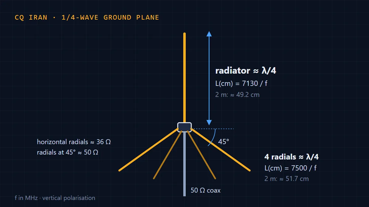
Overview
What is a ground plane?
A ground plane (GP) antenna is a quarter-wave vertical radiator with several equal wires or rods, called radials, at its base. A quarter-wave vertical needs a ground to work against; the radials provide that ground artificially, so the antenna does not need real earth and can sit on a mast or a roof.
The quarter-wave ground plane is the simplest omnidirectional antenna for VHF and UHF, and an excellent choice for working repeaters, handhelds and mobiles, which are all vertically polarised.
How it works
The radiator and radials act together like a dipole whose lower half has been spread out. Being vertical, it radiates equally in all horizontal directions. Current is highest at the base of the radiator, so the base impedance is low and coax connects directly: centre to the radiator, shield to the radials.
The radial angle sets the impedance: horizontal radials give about 36 Ω, and drooping them raises it. At about 45° the impedance reaches 50 Ω, a perfect match to standard coax.
Length formulas and dimensions
Radiator and radial lengths in centimetres for a frequency in MHz:
Radiator: L = 7130 / fRadials: L = 7500 / f
The radiator is about 5% shorter than a true quarter wave because of the end effect; the radials are cut a little longer and are not critical. Examples:
- 6 m (50.2 MHz): radiator about 142 cm, radials about 149 cm
- 2 m (145 MHz): radiator about 49.2 cm, radials about 51.7 cm
- 70 cm (435 MHz): radiator about 16.4 cm, radials about 17.2 cm
Measure the radiator from its tip to where it joins the connector. A thicker rod tunes slightly shorter, so cut a little long and trim.
Materials and construction
- A panel-mount SO-239 (or N) connector with four screw holes
- 2–3 mm brass or copper rod, or 2.5–4 mm² solid copper wire, for the radiator
- Four similar pieces for the radials, with ring terminals
- Four small nuts and bolts, a soldering iron and solder
- A plastic or PVC tube to hold the antenna on the mast
Solder the radiator into the connector’s centre pin. Form a loop at the end of each radial and bolt it to one of the connector’s four holes (the radials reach the coax shield through the connector body). Space the radials evenly and bend them down about 45°. Seal the solder joint and the connector so moisture cannot get into the coax.
Installation
On VHF and UHF range depends mostly on line of sight, so height matters most. Mount the antenna as high as possible, away from metal and walls. Run the coax straight down between the radials. For long runs use low-loss cable (such as RG-213 or LMR-400); on 70 cm, RG-58 loses a noticeable amount every 10 m.
SWR tuning
Measure SWR at mid-band. If the lowest SWR is below the frequency you want, the radiator is too long and must be shortened; if above, it is too short. Trim only a few millimetres at a time. If SWR stays above 1.5 across the band, change the radial angle: drooping them further raises the impedance.
Pros and cons
- Pros: very simple and cheap to build, a direct match to 50 Ω coax, omnidirectional, and no real ground needed.
- Cons: low gain (a collinear or 5/8-wave reaches further), single-band, and protruding radials that need room on a crowded balcony or roof.
Common mistakes
- Measuring the radiator from the connector’s edge instead of the joint
- Not sealing the connector, so the coax fails after a few rains
- Mounting the antenna below roof level or beside a concrete wall
- Using a long, lossy cable, especially on 70 cm
Quarter-wave ground plane (GP) antenna specs
- Gain
- About 2 dBi (close to a dipole)
- Feed-point impedance
- 36 Ω with horizontal radials; about 50 Ω with radials at 45°
- Polarization
- Vertical
- Radiation pattern
- Omnidirectional in the horizontal plane
- Front-to-back ratio
- None (0 dB)
- Bandwidth
- The whole 2 m band with SWR below 1.5
- Approximate size
- 2 m: radiator about 49 cm, radials about 52 cm
- Tuner needed
- No
- Build difficulty
- Easy
Figures are approximate; they depend on construction, mounting height and surroundings.