Knowledge base
An amateur radio reference: antenna types and equipment, with specs, plain explanations and comparisons.
Antennas
Amateur radio antenna types, from a simple dipole to a Yagi: how they work, specs, building tips and comparisons.
HF wire antennas
For shortwave (3–30 MHz): cheap, light and built from wire and a few insulators — most hams’ first antenna.
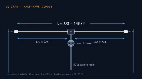
Half-wave dipole antenna
The simplest and most fundamental antenna: two equal wires fed in the middle with coax. Cheap, built in an afternoon, and the reference every other antenna is c...
Specs and details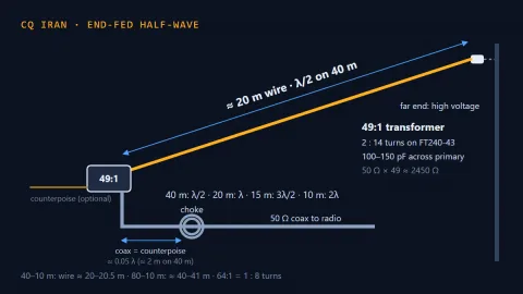 Coming soon
End-fed half-wave (EFHW) antenna
A half-wave wire fed at one end through a 49:1 transformer. About 20 m of wire covers 40, 20, 15 and 10 m without a tuner, and with the feed point at one end it...
Coming November 10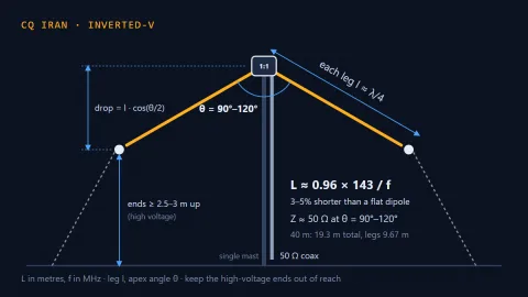 Coming soon
Inverted-V dipole antenna
A dipole whose centre goes up a single mast while the two legs slope down. It needs only one tall support, matches 50 Ω coax almost directly, and is an excellen...
Coming November 16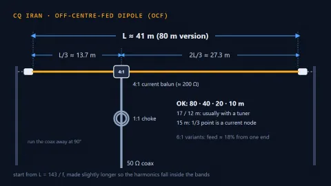 Coming soon
Off-centre-fed dipole (OCF / Windom)
A dipole fed about one third of the way along instead of at the centre, through a 4:1 balun and coax. A wire of about 41 m works 80, 40, 20 and 10 m without a t...
Coming November 25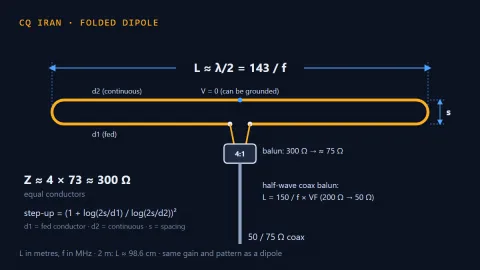 Coming soon
Folded dipole antenna
A half-wave dipole with a second parallel conductor joining its ends. Same gain and pattern as a dipole, but about 300 Ω and wider bandwidth — the usual driven...
Coming December 10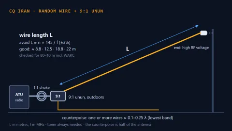 Coming soon
Random wire antenna with a 9:1 unun
A wire of “non-resonant” length, a 9:1 unun at its base, a counterpoise and a tuner. The simplest way onto several HF bands when you have only one high point —...
Coming December 19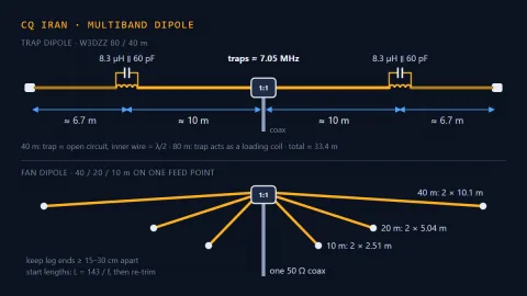 Coming soon
Multiband dipole: trap and fan dipoles
Two classic ways to work several bands with one dipole and one coax, without a tuner: the trap dipole, such as the W3DZZ for 80 and 40 m, and the fan dipole, se...
Coming December 28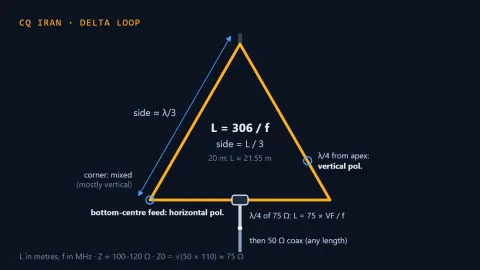 Coming soon
Full-wave loop and delta loop antenna
A closed loop of wire one wavelength long, shaped as a triangle, a square or anything in between. About 1 dB more gain than a dipole, a single support for an ap...
Coming December 31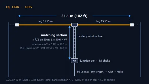 Coming soon
G5RV antenna
A 31 m dipole with a ladder-line matching section and then coax, designed by Louis Varney. It works on 20 m without a tuner and on the rest of 80–10 m with one:...
Coming January 9HF verticals and compact antennas
When there is no room for a long wire: a small roof, a balcony or a car.
 Coming soon
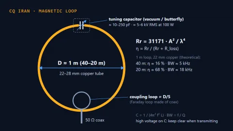
Small transmitting magnetic loop antenna
A loop of copper tube about a metre across and a high-voltage variable capacitor: an antenna that fits on a balcony and covers several HF bands. Its bandwidth i...
Coming December 1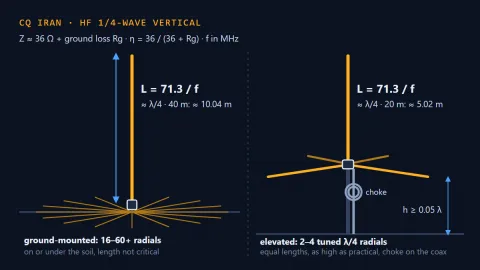 Coming soon
HF quarter-wave vertical with radials
A quarter-wave vertical tube or wire fed at its base and working against a radial system. A low radiation angle and an omnidirectional pattern for DX on a small...
Coming December 16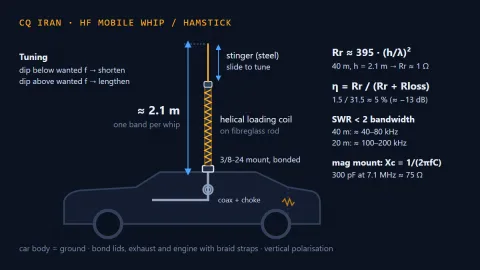 Coming soon
HF mobile whip and Hamstick antennas
A short loaded whip mounted on a car, using the car body as its ground. Compact and cheap, but very narrow-band and inefficient on the low bands; correct mounti...
Coming January 12Omnidirectional VHF/UHF antennas
The 2 m and 70 cm bands: for handhelds, mobiles, base stations and repeater work.
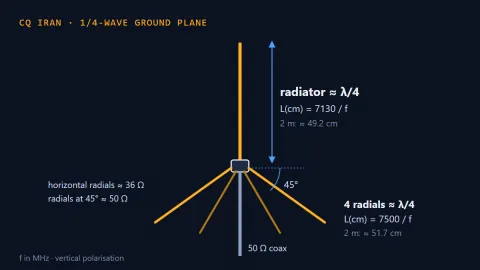
Quarter-wave ground plane (GP) antenna
A quarter-wave vertical rod plus a few radials that form an artificial ground. The simplest omnidirectional base antenna for 2 m and 70 cm, built in an hour fro...
Specs and details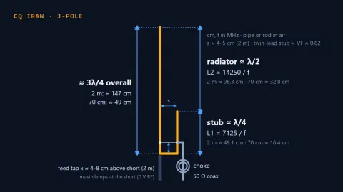 Coming soon
J-pole antenna
An end-fed vertical half-wave matched through a quarter-wave stub, with no radials. Built from copper pipe or 300 Ω twin-lead, it is one of the most popular hom...
Coming November 7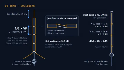 Coming soon
Collinear antennas: coaxial and dual-band
Several half-wave elements stacked in a vertical line and fed in phase, so the radiation is squeezed towards the horizon. From the home-built coaxial collinear...
Coming November 22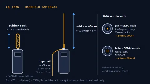 Coming soon
Handheld (HT) radio antennas
The short rubber antenna supplied with a handheld is convenient but several decibels weaker than a full-size antenna. A longer whip, a "tiger tail" wire or an e...
Coming November 28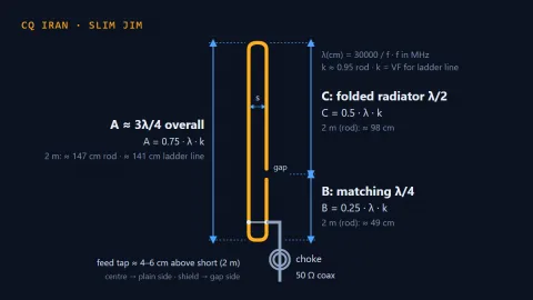 Coming soon
Slim Jim antenna
A J-pole variant with a folded half-wave radiator and a quarter-wave matching section, all in one narrow loop. Built from rod or ladder line with no radials; th...
Coming December 7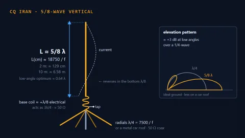 Coming soon
5/8-wave vertical antenna
A vertical radiator of about 0.64 λ with a matching coil at its base, on a car roof or a few radials. On a good ground it puts about 3 dB more than a quarter-wa...
Coming December 25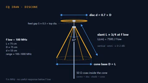 Coming soon
Discone antenna
A disc on top of a cone that covers roughly a ten-to-one frequency range with no tuning. The classic scanner and SDR antenna; it can also transmit on amateur ba...
Coming January 3Directional antennas (beams)
More gain in one direction: DX, low-earth-orbit satellites, contests and fox hunting.
 Coming soon
Yagi-Uda beam antenna
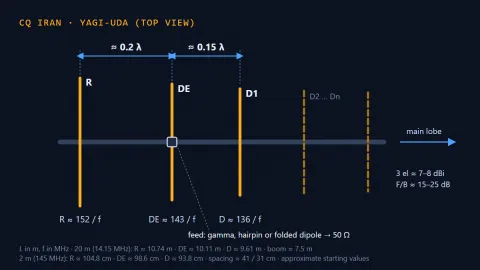
The most widely used directional antenna in amateur radio: a driven element, a reflector behind it and one or more directors in front, on a boom. From a 3-eleme...
Coming November 13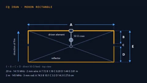 Coming soon
Moxon rectangle antenna
A two-element beam whose element ends are folded inward into a rectangle. It gives roughly the gain of a two-element Yagi, but with a far better front-to-back r...
Coming November 19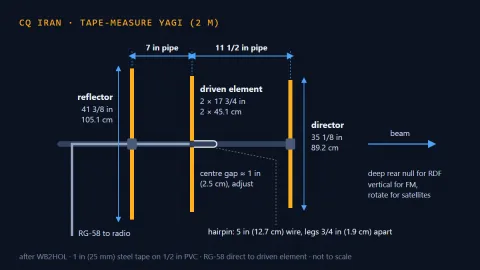 Coming soon
Tape-measure Yagi
A handheld 3-element Yagi for 2 m with elements cut from a steel tape measure, clamped to PVC pipe. Cheap and light, it bends and springs back when it hits a br...
Coming December 4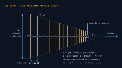 Coming soon
Log-periodic dipole array (LPDA)
A row of dipoles whose lengths and spacings shrink by a constant ratio, fed by a criss-crossed line. It keeps roughly constant gain and impedance over a very wi...
Coming December 13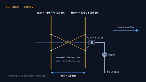 Coming soon
HB9CV antenna
A small two-element beam with both elements driven, joined by a crossed phasing line. Its short boom, light weight and deep rear null have made the HB9CV the st...
Coming December 22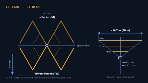 Coming soon
Hex beam antenna
A two-element wire Yagi with its elements bent into W and M shapes and strung on six fibreglass spreaders like an inverted umbrella. It covers five or six bands...
Coming January 6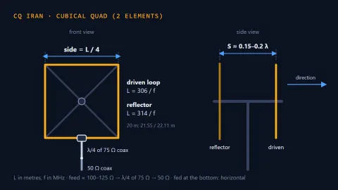 Coming soon
Cubical quad antenna
A beam made of full-wave wire loops instead of straight Yagi elements. A two-element quad gives roughly the gain of a three-element Yagi on a shorter boom, and...
Coming January 15