Half-wave dipole antenna
The simplest and most fundamental antenna: two equal wires fed in the middle with coax. Cheap, built in an afternoon, and the reference every other antenna is compared against.
Last updated:
Overview
What is a half-wave dipole?
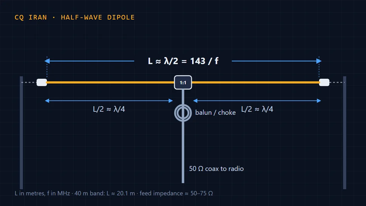
A half-wave dipole is two equal wires or tubes in a straight line, fed in the middle. Its total length is about half a wavelength at the operating frequency, so each leg is roughly a quarter wavelength. The dipole is the theoretical basis of almost every antenna, and other antennas’ gain is often quoted relative to it (in dBd).
Because it is simple, cheap and predictable, the dipole is usually the first HF antenna a new ham builds — and many experienced operators keep working the world with one for years.
How it works
When the dipole is half a wavelength long it is resonant: current is highest at the centre and lowest at the ends, while voltage is the opposite, highest at the ends. That is why the centre has a low impedance (about 73 Ω in free space) and is easy to feed with 50 Ω coax.
Maximum radiation is broadside to the wire, with almost nothing off the ends, giving a figure-8 pattern seen from above. You only get that pattern when the antenna is high; a dipole lower than a quarter wavelength radiates in nearly all directions, mostly upward.
Length formula and sizes per band
The total length in metres for a frequency in MHz is:
L = 143 / f
143 is 150 (half a wavelength in free space) reduced by about 5% for the end effect: a real wire has thickness, and its ends behave as if slightly longer than they are. Each leg is half of the total. Examples:
- 80 m (3.65 MHz): about 39.2 m total, 19.6 m per leg
- 40 m (7.1 MHz): about 20.1 m total, 10.1 m per leg
- 20 m (14.2 MHz): about 10.1 m total, 5.04 m per leg
- 15 m (21.2 MHz): about 6.75 m total, 3.37 m per leg
- 10 m (28.5 MHz): about 5.02 m total, 2.51 m per leg
These are starting points. Height, nearby objects, wire type and insulation all shift the final length by a few percent, so always cut the wire a little long and trim.
Materials and construction
- Stranded or solid copper wire, 1.5–2.5 mm² (ordinary house wire works)
- A centre insulator (or a feed box with an SO-239 connector) and two end insulators
- A 1:1 current balun or a coax choke
- 50 Ω coax (RG-58 for short runs; RG-213 or LMR-400 for long runs and higher power)
- UV-resistant rope for the ends
Cut both wires about 5% longer than calculated. Fix one end of each to the centre insulator and pass the other end through an end insulator and back, so the spare wire can later be trimmed or folded back. The coax centre goes to one leg, the shield to the other. Seal the connections against moisture.
Feeding, balun and choke
A dipole is balanced; coax is unbalanced. Connected directly, part of the current returns on the outside of the shield and the coax radiates as part of the antenna. The result: a skewed pattern, household noise in the receiver and RF coming back into the shack (tingling microphones, misbehaving equipment).
The cure is a 1:1 current balun at the feed point — for example 8–12 turns of thin coax on an FT240 toroid of mix 31 or 43 — or, more simply, a few turns of coax coiled about 15 cm across just below the antenna (an air choke, most effective on the higher bands).
Installation and height
Mount the dipole as high as you can, away from power lines, metal gutters and concrete walls. A quarter wavelength is a sensible minimum. For short-range contacts on 40 and 80 m, a fairly low dipole (about 0.1–0.2 λ) works even better because of its upward NVIS radiation; for DX, half a wavelength or more is ideal.
If you only have one tall support, raise the centre and bring the ends lower — that is the inverted-V, covered in its own article. The ends of a dipole carry high voltage; keep them out of people’s reach.
Tuning the SWR by trimming
With an antenna analyser, or the radio and an SWR meter, find the frequency of lowest SWR. If it is below the frequency you want, the antenna is too long and must be shortened; if above, it is too short. The new length is roughly:
L(new) = L(now) × f(measured) / f(wanted)
Take the difference equally from both legs, in small steps. Measure at the final height; an antenna tuned near the ground shifts frequency once it goes up.
Pros and cons
- Pros: very cheap and simple, no tuner needed on its band, predictable, an almost direct match to 50 Ω coax, and no ground system or radials.
- Cons: long on the low bands (about 40 m for 80 m), single-band, and needs two high supports to perform well.
Common mistakes
- No balun or choke, so the coax radiates and noise is high
- Tuning the antenna low and then raising it
- Trimming one leg instead of both equally
- Running the legs past gutters, railings or wiring
- Cutting the wire exactly to the formula, leaving nothing to tune with
Half-wave dipole antenna specs
- Gain
- 2.15 dBi in free space (0 dBd)
- Feed-point impedance
- About 73 Ω; 50–90 Ω depending on height
- Polarization
- Horizontal
- Radiation pattern
- Bidirectional (figure-8); nearly omnidirectional when low
- Front-to-back ratio
- None (0 dB)
- Bandwidth
- About 3–5% of frequency with SWR below 2
- Approximate size
- 40 m band: about 20 m long
- Tuner needed
- No (on its design band)
- Build difficulty
- Easy
Figures are approximate; they depend on construction, mounting height and surroundings.